Lesson1-Prepare software and configure the environment
1.Download and Install Arduino IDE
Open the Arduino IDE Software page using your browser:
https://www.arduino.cc/en/software
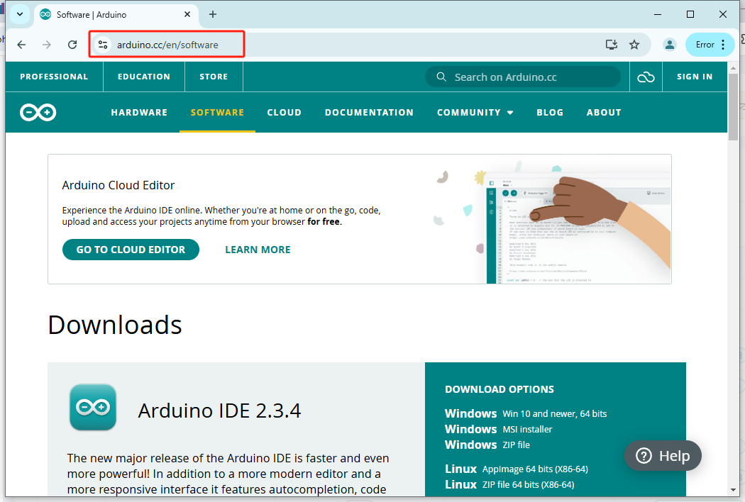
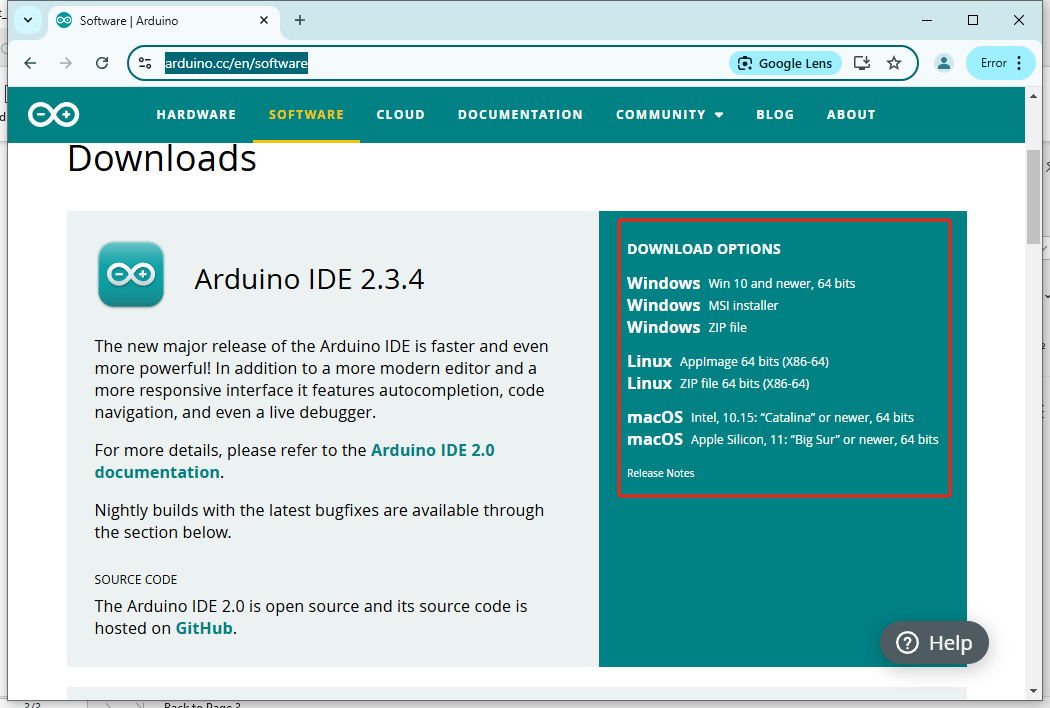
On the right side, you will see a list of installation packages. Download the corresponding package based on your operating system. If you are using Windows like me, I recommend downloading the MSI Installer, as it will automatically install for us without any manual steps, making it very convenient. The first installation package requires manual installation and allows you to customize the installation path, while the third one is a portable version, which I do not recommend using. So, click the "Windows MSI installer".
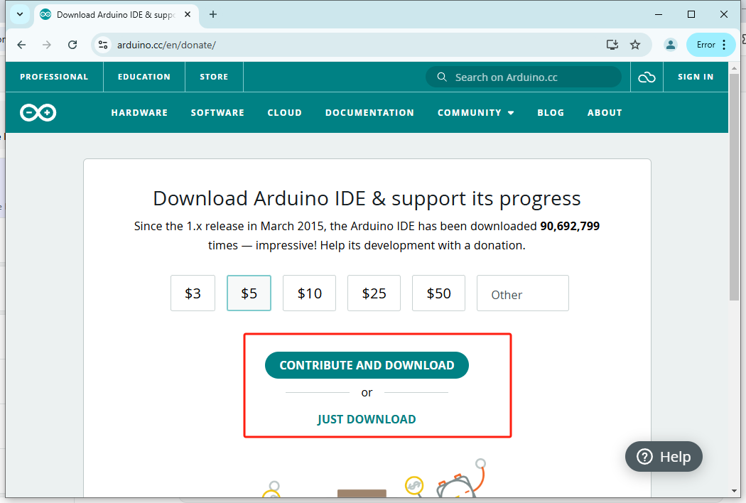
Here, you can contribute your part or simply click "Just Download" to skip the prompt.
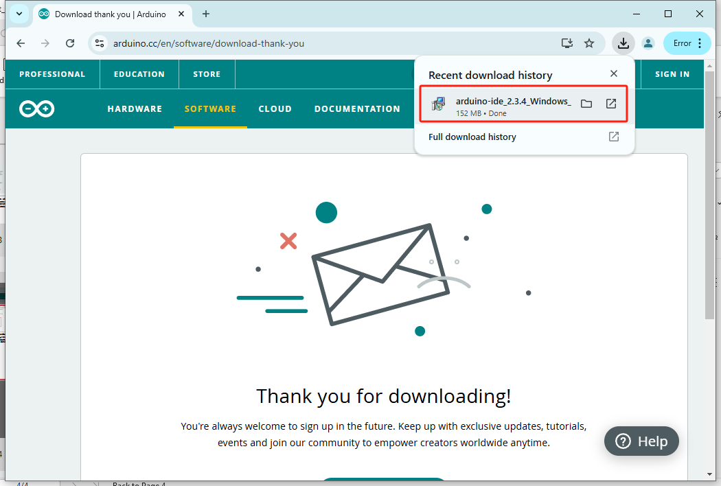
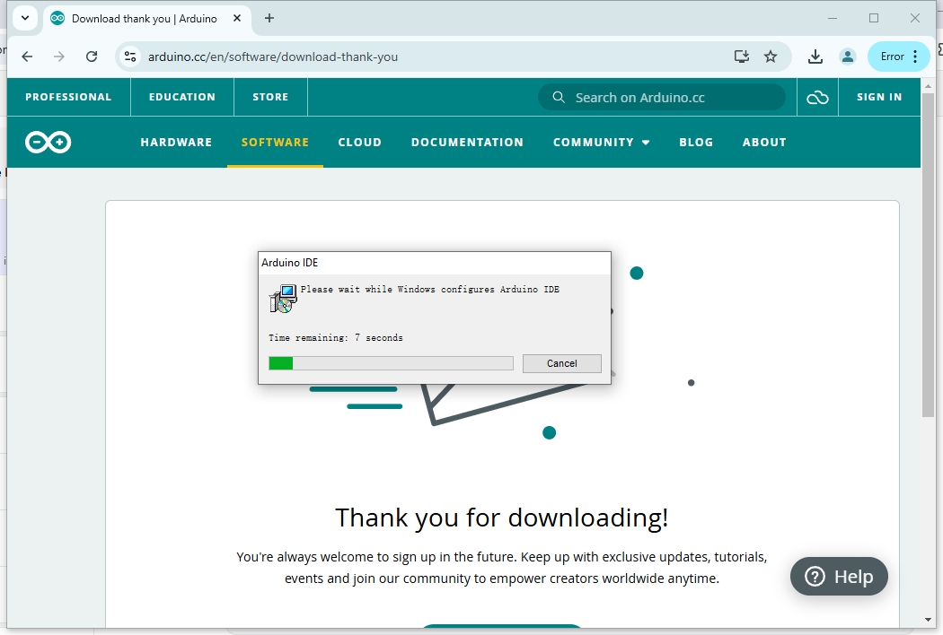
Once the installation package is downloaded, click to run it.
When the MSI installer runs, it will automatically install the Arduino IDE. You won't need to perform any manual steps during the process; just wait for about a minute.
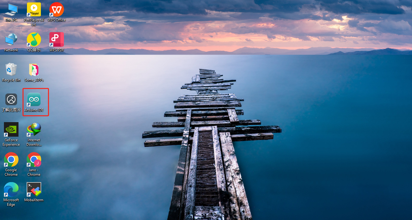
When you notice that the MSI installer has disappeared and you can see the Arduino IDE icon on your desktop, it means the installation is complete. Let's run it.
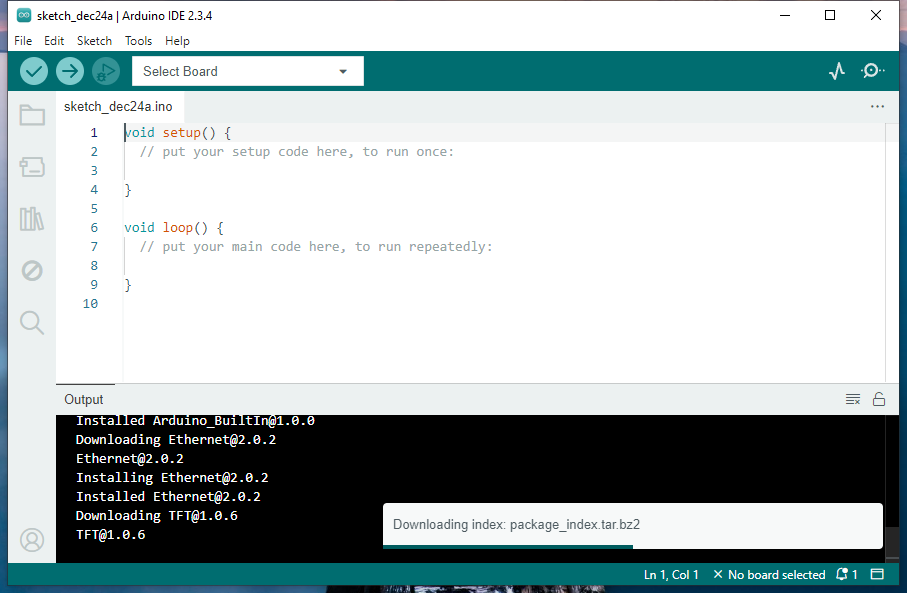
If you're installing and running the Arduino IDE for the first time like I am, it will automatically download and install the Arduino development packages. During this process, it will prompt you to agree to install some drivers, and it's essential to choose "Agree," as our ESP32 Pixel board also requires these drivers. Since I can't capture a screenshot of the prompt asking about the drivers, I can only emphasize this point through text.
Once the Arduino development packages and drivers are installed, the progress bar in the lower right corner will disappear.
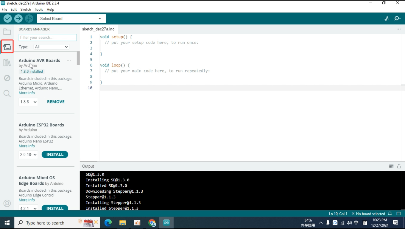
Once the Arduino development packages and drivers are installed, the progress bar in the lower right corner will disappear. Additionally, when you click on this icon in the toolbar to open the Boards Manager, you will see that the Arduino development packages are displayed as installed.
However, we still need to enable the Arduino IDE to support development for boards equipped with the ESP32 chip, so we need to install the ESP32 development package. If you search directly, you won't be able to find the ESP32 development package provided by Espressif. Therefore, we need to inform the IDE where to find this installation package.
2.Configure the ESP32 development environment
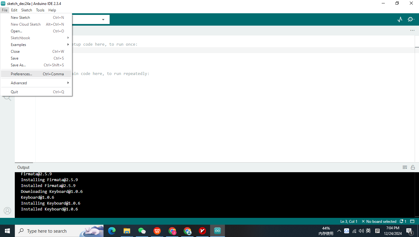
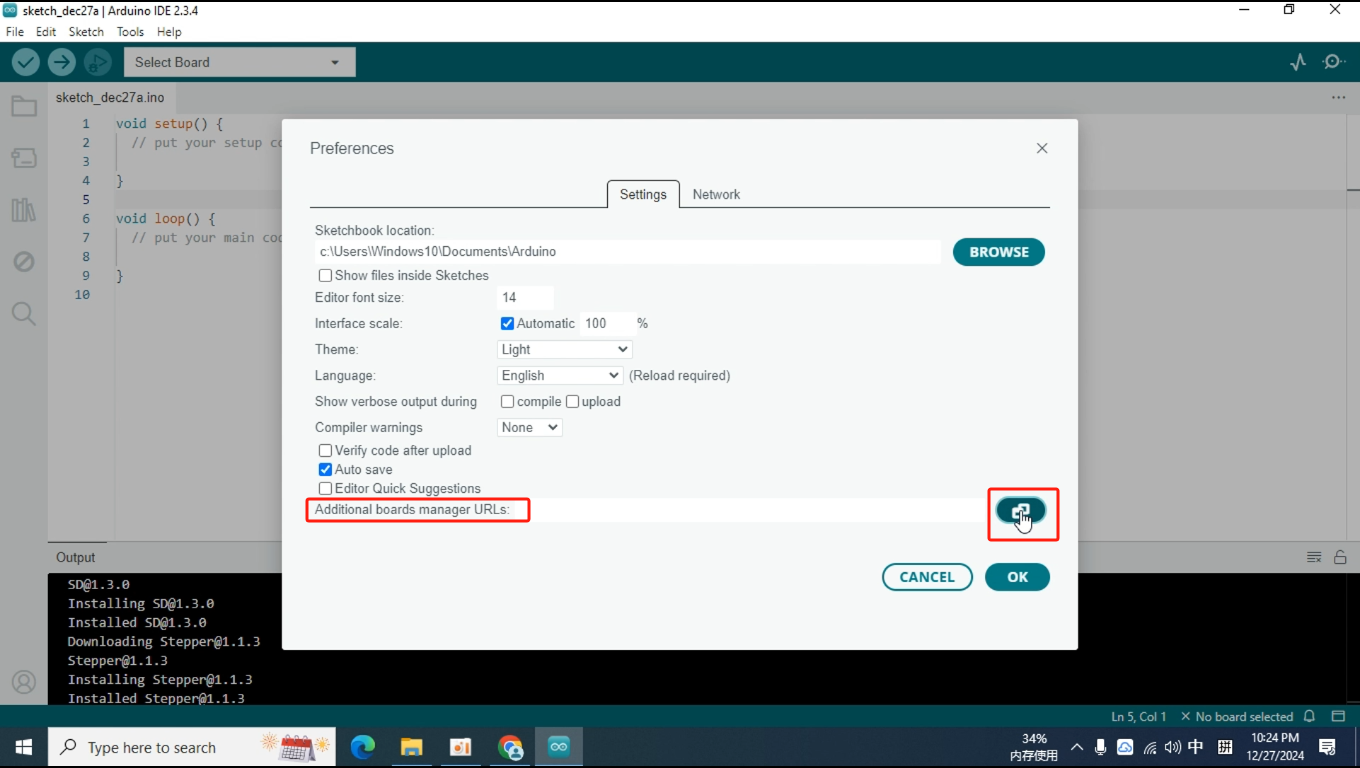
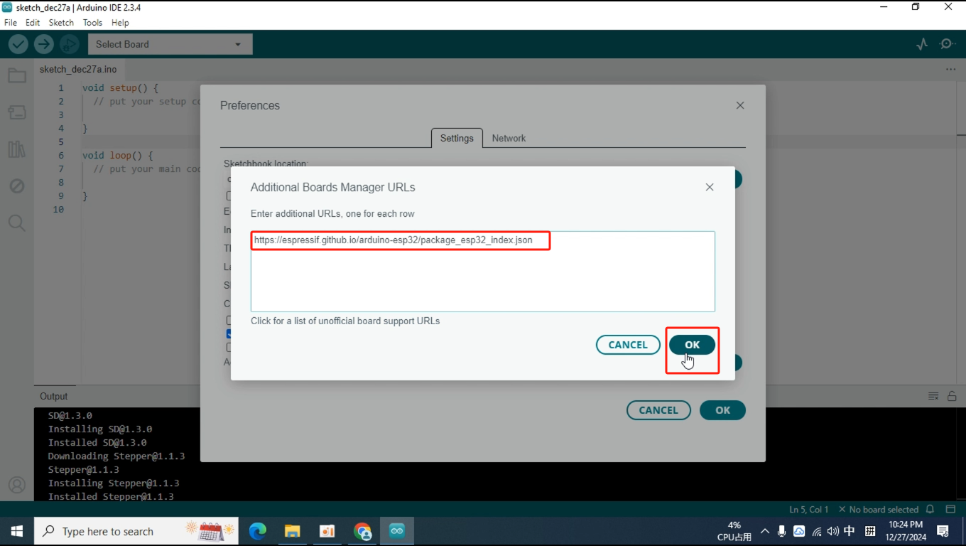
Click on "File," open "Preferences," and then find "Additional Boards Manager URLs." There is a button to the right of it; click on that.
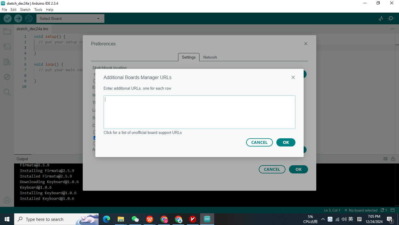
If this is your first time installing the Arduino IDE like me, this section will be blank. You need to enter the JSON file link for the ESP32 development package here so that the IDE knows where to retrieve the information for the various versions of the ESP32 development package.
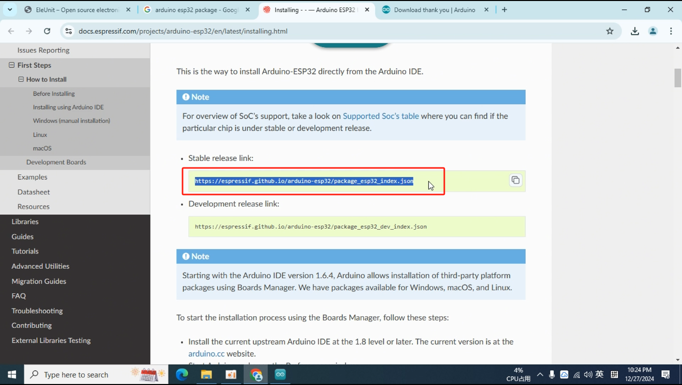
Open a browser, copy the following URL into the address bar, and navigate to that page.
https://docs.espressif.com/projects/arduino-esp32/en/latest/installing.html
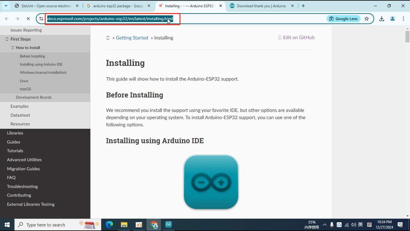
Scroll down and find the link under "Stable release link," then copy it.
https://espressif.github.io/arduino-esp32/package_esp32_index.json
Paste the copied link here, then click OK.
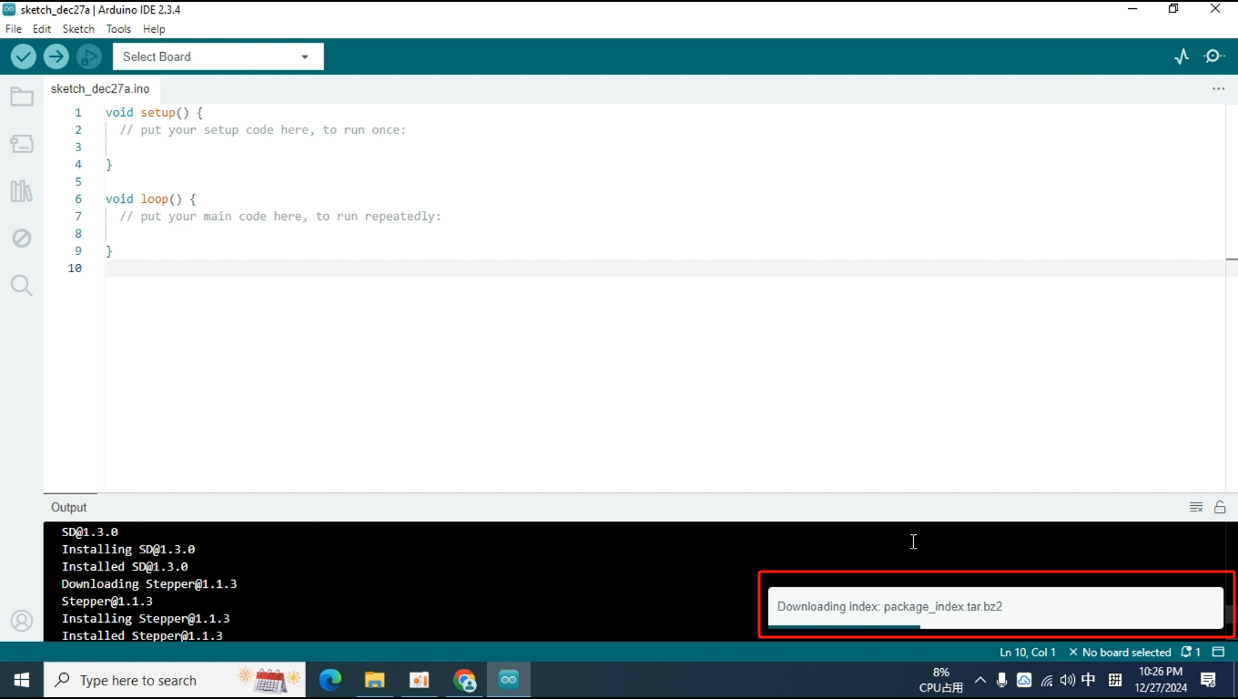
Once the Arduino IDE detects that you have submitted an external board JSON link, it will automatically download the JSON file. The download progress is displayed in the bottom right corner. When the progress bar disappears, it means the download is complete.
Open the Boards Manager again and search for ESP32. Now the Arduino IDE can find the ESP32 development package provided by Espressif.
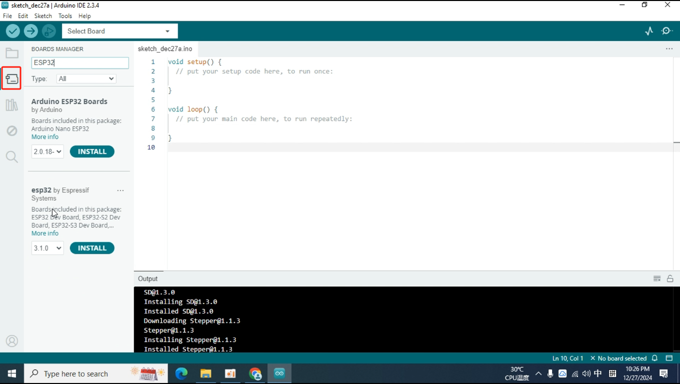
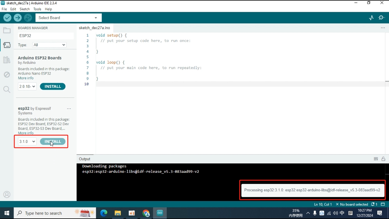
The latest version of the ESP32 board is 3.1.0, and it will be selected by default. We just need to click "Install." After the installation begins, a progress bar will appear in the bottom right corner. Since the development package is quite large, the installation process may take some time, so please be patient.
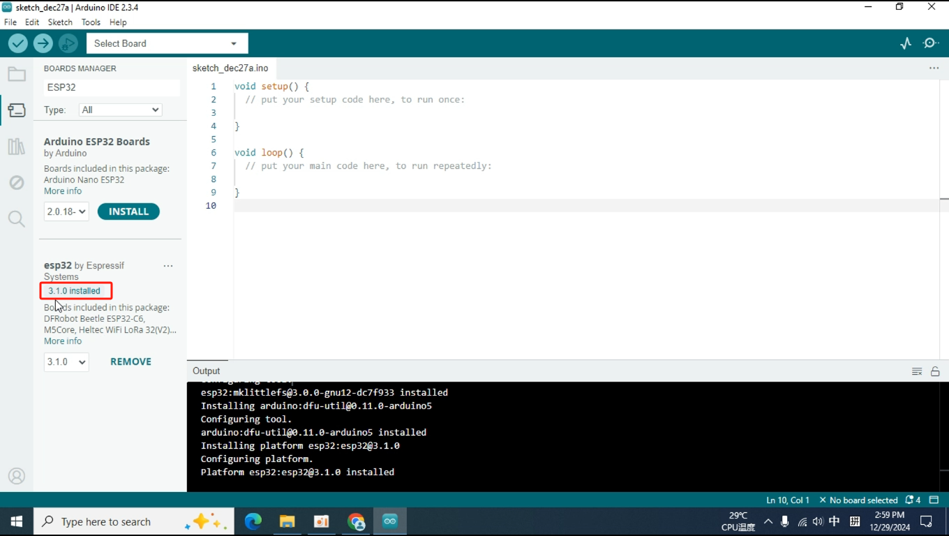
Once the progress bar disappears, you will see that the ESP32 development package shows "installed." You can then proceed to develop for all boards equipped with the ESP32 chip.
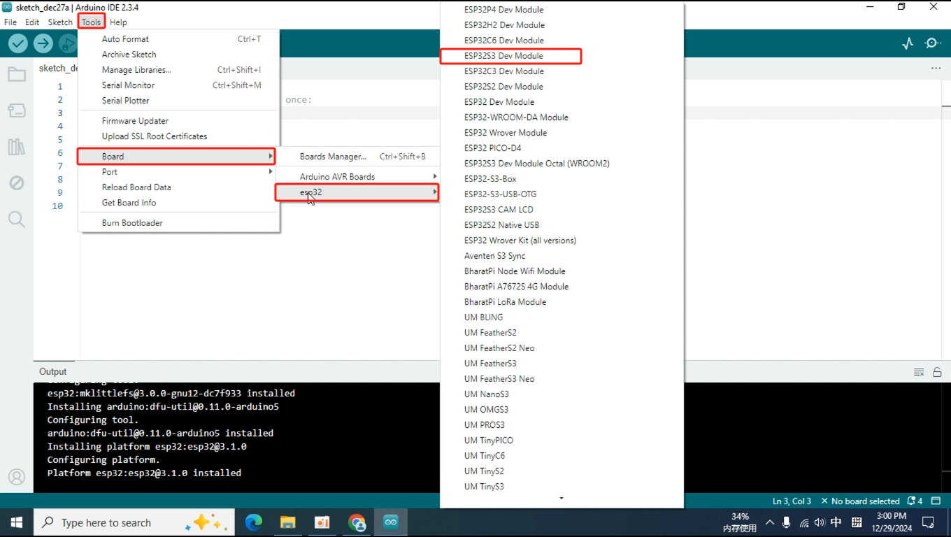
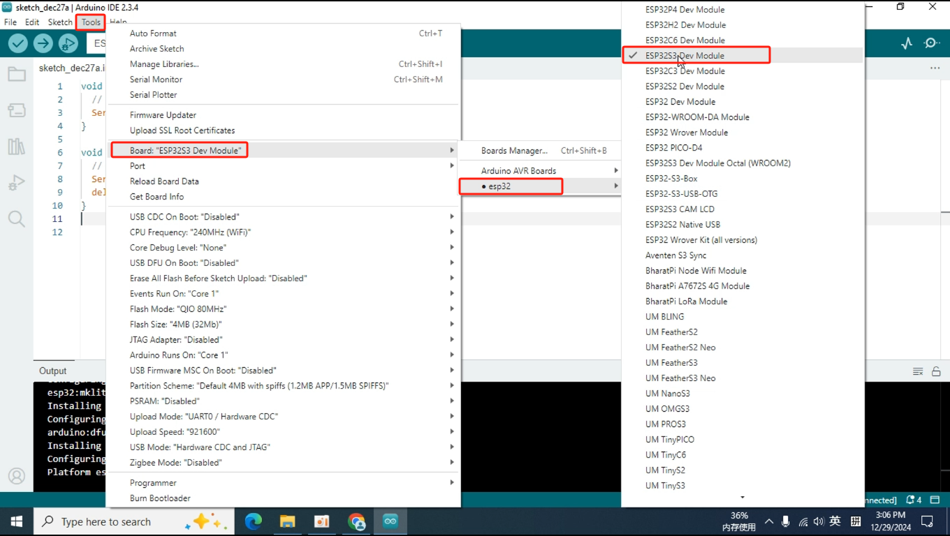
When you click on Tools and scroll to the Boards option, you will find that the IDE already includes many options for ESP32 boards. Since our Pixel board uses the ESP32S3 chip, the corresponding board option is "ESP32S3 Dev Module," which we will select. (This step is part of configuring the compilation environment, and you can do it after writing the code. I'm mentioning it here just to make you aware of the changes in the IDE after installing the development package.)
3.Write code
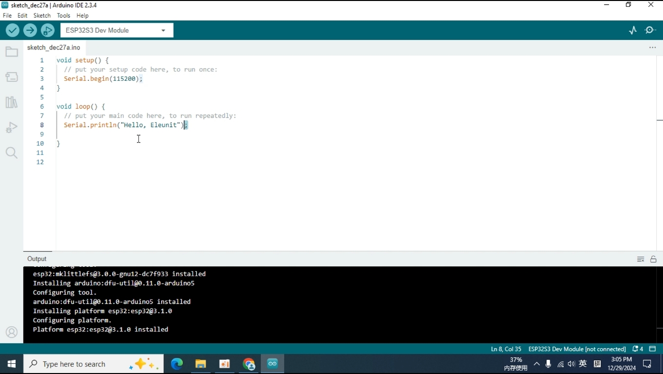
Next, we need to write some code to test whether the Arduino IDE can upload the code to the Pixel board and drive it to operate normally. Let's start with the simplest example: having the Pixel board send "Hello, Eleunit" to the computer via the serial port.
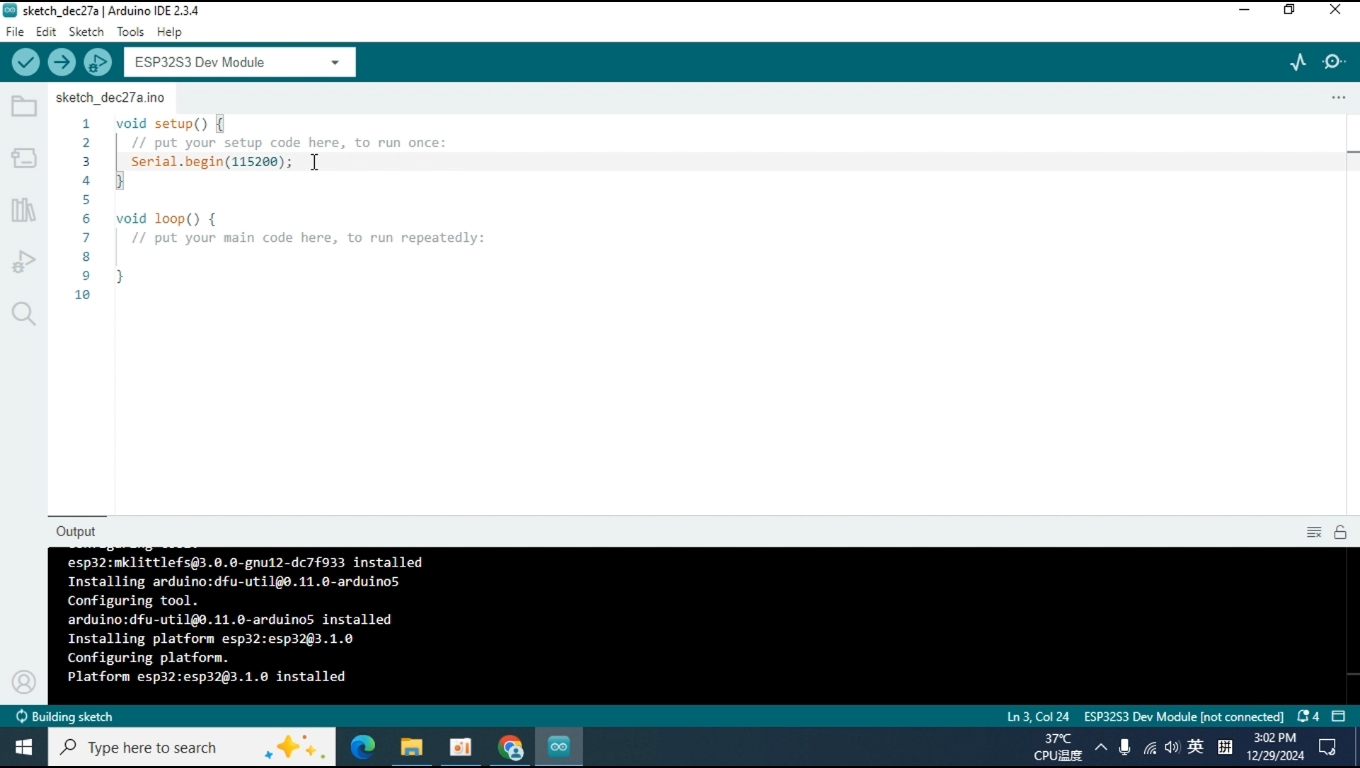
In the setup function, use the Serial.begin function to initialize the serial port. The Serial.begin function has one parameter that we need to set, which is the baud rate; we will set the baud rate to 115200.
After the serial port is initialized, we can send text from the serial port in the loop function. You might wonder why we need to place the serial initialization function in the setup function while sending text is done in the loop function. That's a good question! The setup function only runs once when the board is powered on. After the setup function finishes executing, the code in the loop function is continuously executed in a repeating cycle.
Both the print and println functions are used to print text information, but the println function adds a carriage return and a newline after printing the text. To make the text look neater, I will use the println function for demonstration.
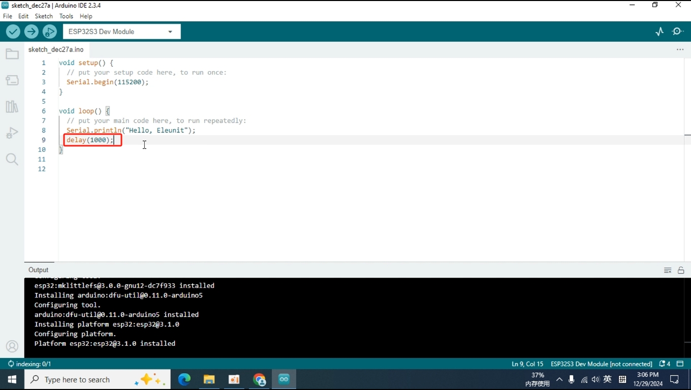
To make the received information clearer on the computer, I added a delay function and set the parameter to 1000, which means 1000 milliseconds. This means that "Hello, Eleunit" will be printed once every second.
The code is now written, but before uploading it, we need to configure the compilation environment to ensure that the code can be compiled and uploaded to the board correctly and run smoothly.
4.Configure the Compilation Environment
Click on Tools, expand the ESP32 options under Boards, and select the ESP32S3 Dev Module based on the hardware design of the Pixel board.
Connect the Pixel board to the computer using a USB Type-C cable, and turn on the power switch of the Pixel board.
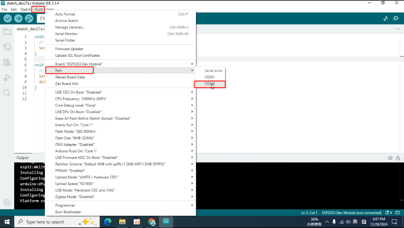
Back in the Arduino IDE, click on Tools, then select the port corresponding to the Pixel board under Port. On my computer, it's COM4, but on yours, it might be COM2, COM9, or another number, as this is assigned by the computer.
(COM1 is my wireless network adapter. You can check the currently assigned port numbers before connecting the Pixel board, and the new port number that appears after connecting it will correspond to the Pixel board.)
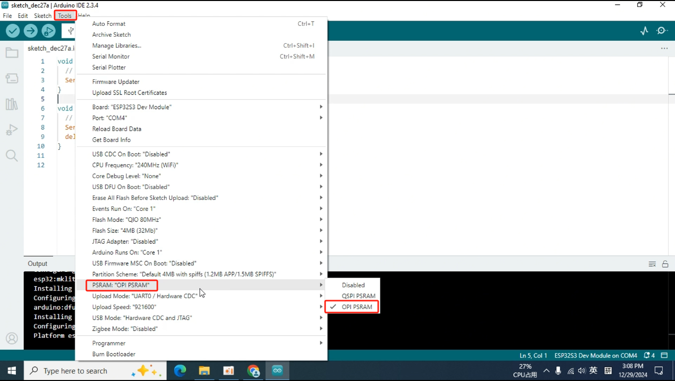
Next, still in Tools, locate the PSRAM option and select OPI PSRAM. If you make a mistake at this step, the code may compile and upload successfully, but the board will not run correctly.
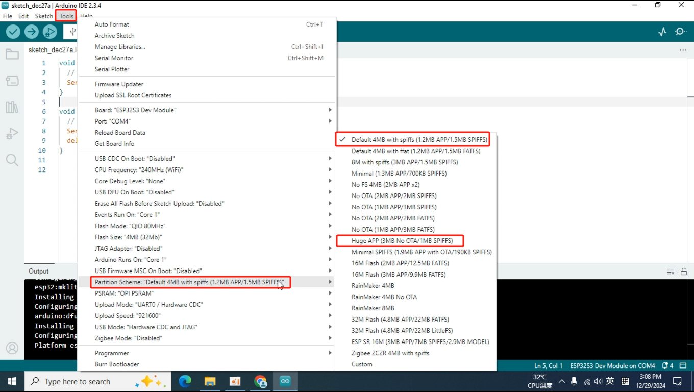
For the final step, find the Partition Scheme in Tools and select Default or Huge APP.
(Since the program we are currently writing is relatively simple, this option can be chosen somewhat freely. However, in later lessons, we will be using LVGL, which will require more Flash space, so we will need to select Huge APP.)
Great! With the compilation environment set up, we can now proceed to upload the code.
5.Upload Code
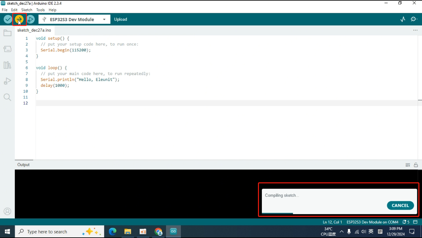
Click on the icon in the top left corner to upload the code.
The progress bar in the bottom right corner shows the status of the code compilation and upload.
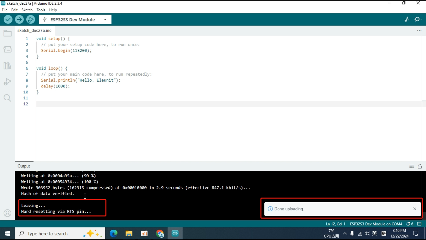
Once the upload is successful, the progress bar in the bottom right corner will display a message and then disappear. The output window will prompt you to reset the board, but our Pixel board has been designed to automatically reset after the code upload, so manual resetting is not necessary.
6.Testing
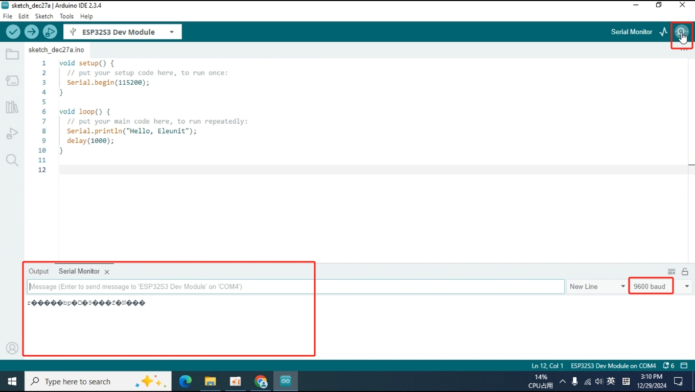
Click on the magnifying glass icon in the top right corner to open the serial monitor. You will notice that the information received by the computer in the serial monitor is not what we expected, which is "Hello, Eleunit." This is because the baud rate of the serial monitor is inconsistent with that set on the Pixel board. The Pixel board is initialized with a baud rate of 115200, while the current baud rate of the serial monitor is set to 9600. Therefore, we need to change the baud rate of the serial monitor to 115200 for it to display correctly.
This is because the baud rate of the serial monitor is inconsistent with that set on the Pixel board. The Pixel board is initialized with a baud rate of 115200, while the current baud rate of the serial monitor is set to 9600. Therefore, we need to change the baud rate of the serial monitor to 115200 for it to display correctly.
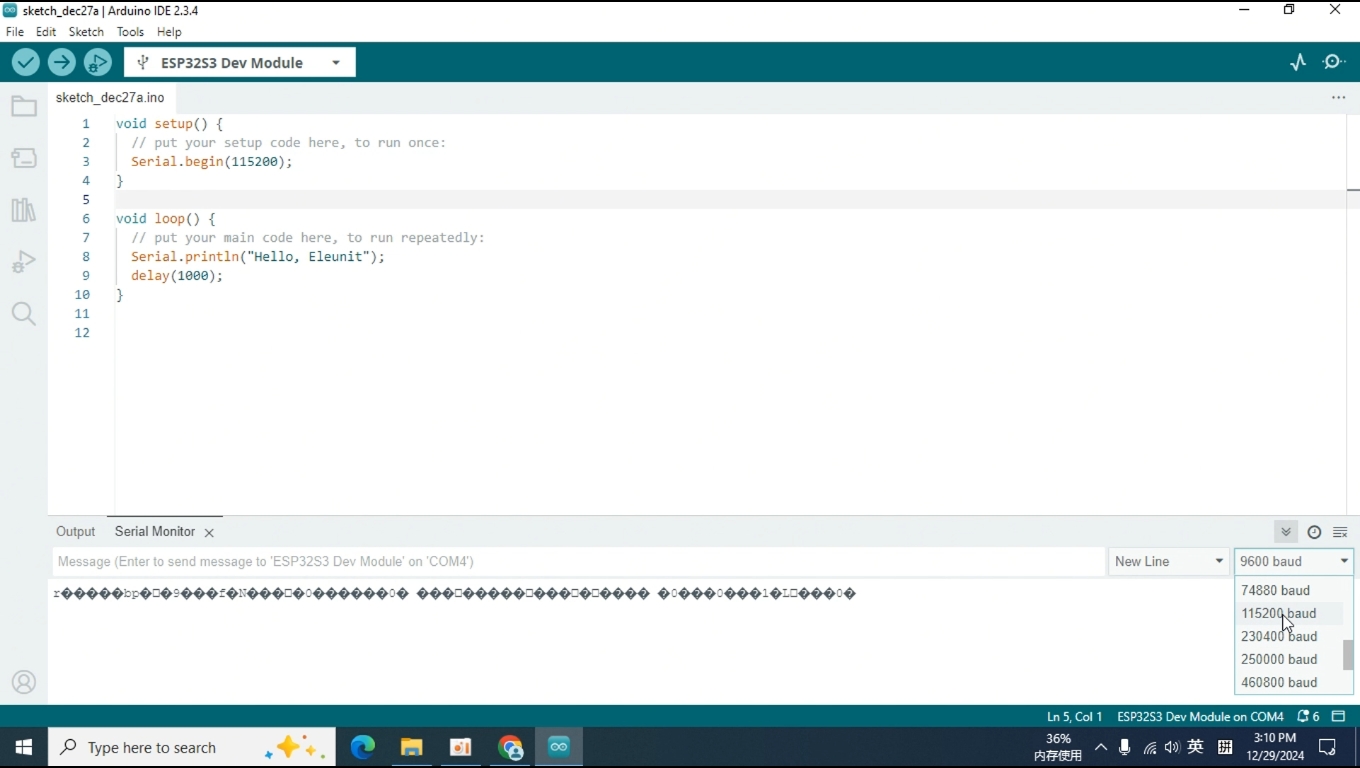
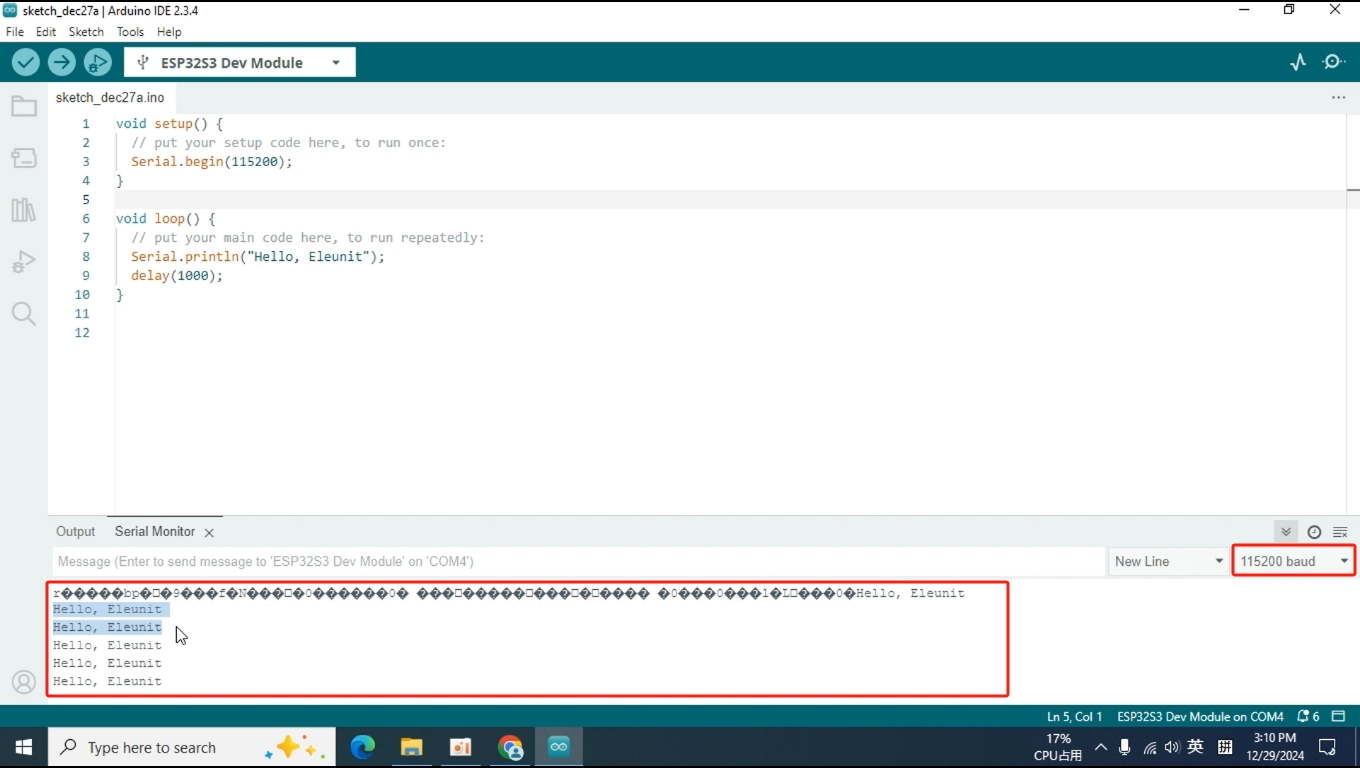
Therefore, we need to change the baud rate of the serial monitor to 115200 for it to display correctly.
End
Alright, that concludes the content of this lesson. If you have any questions, you can post in our forum, and we will respond as soon as we see it. Thank you for watching, and see you in the next lesson!